Magnetization & Demagnetization Performance in Magnetic Particle Inspection
Arora Technologies (P) Limited
Why this Study ?
• Carbon content changes magnetization effort. • Waveform choice affects depth of defect detection. • Large/heavy components need correct kAT and field adequacy. • Residual magnetism impacts machining, bearings, assembly safety. • Demagnetization is not universal; harder steels need stronger or DC reversing demag. • Standards give ranges, but specific guidance for different steels is sparse.
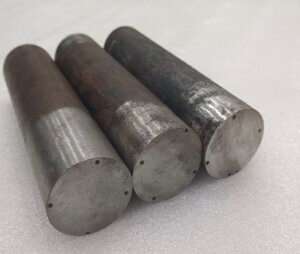
Materials & Specimens:
Steel
Carbon
Magnetic Behaviour
AISI 1020
Low (0.21%)
Easy to magnetize & demag
AISI 1050
Medium (0.48%)
Moderate behaviour
AISI EN31
High (1.09%)
Hard to magnetize & demag
Rod Geometry: 200 mm length × 50 mm diameter
Defects of Geometry :
Location from surface (depth of top of FBH): 0.5 mm / 1.5 mm / 2.5 mm / 3.5 mm
Defect depth (FBH height): 19 mm
Defect diameter: 1 mm
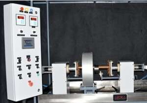
Magnetization Setup
MPI Machine — Model: ABM-4000M capable of delivering up to 4000 A magnetizing current, used for testing.
Circular magnetization (Head / Tail Stock)
Waveforms: AC vs HWDC
Fluorescent wet particles, UV inspection
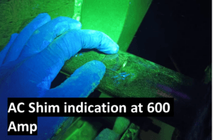
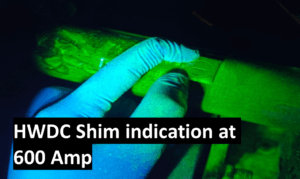
Magnetizing current applied in steps from 600 A up to 1800 A, increasing until field adequacy is demonstrated
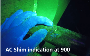
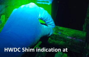
using Shim indicator as per ASME requirements.
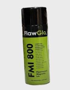
Fluorescent Magnetic Particle Media Used :
Product: FlawGlo FMI 800
Key Properties:
Ultra-bright magnetic particles for very fine discontinuity detection
Particle size: 2–5 µm (avg. ~3 µm) — high sensitivity
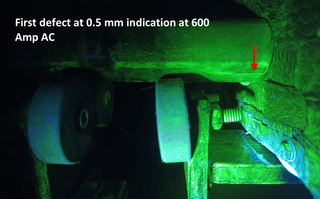
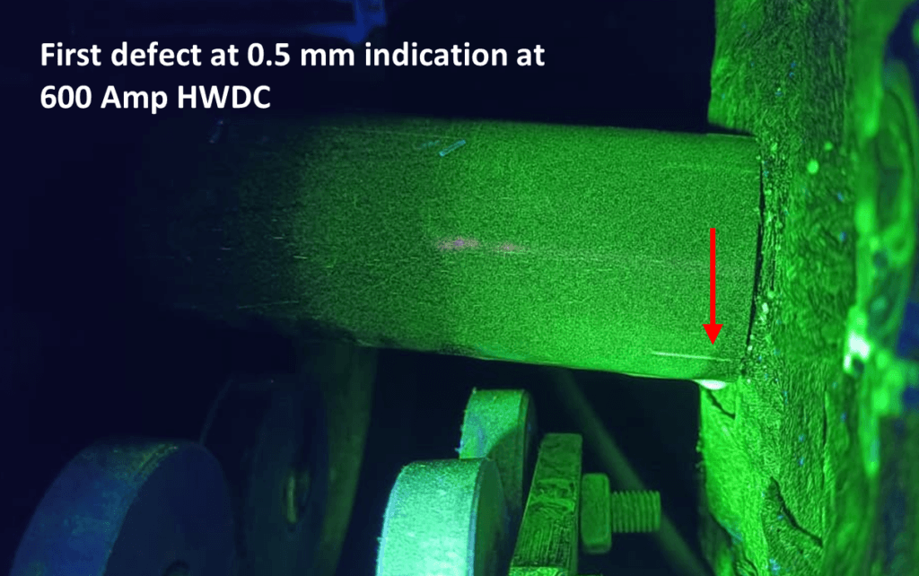
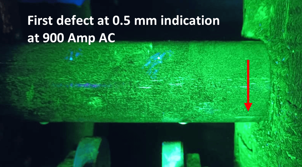
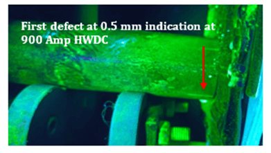
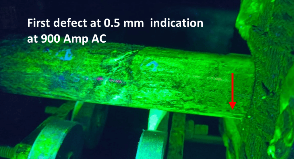
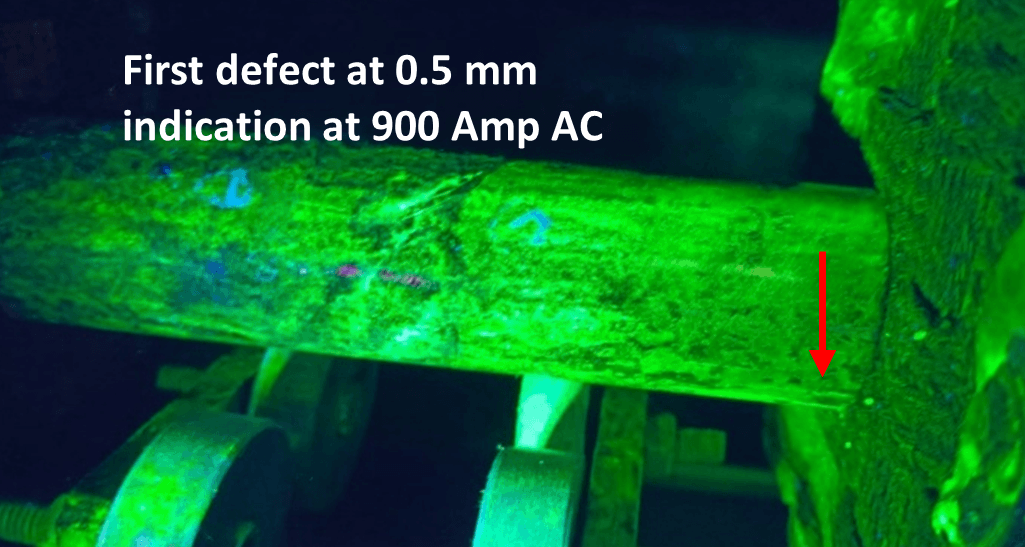
• Surface Sensitivity (D1 – 0.5 mm) 1. Both AC and HWDC provide strong detection consistently at all current levels 2. Shim indication strong at 600 A for both methods
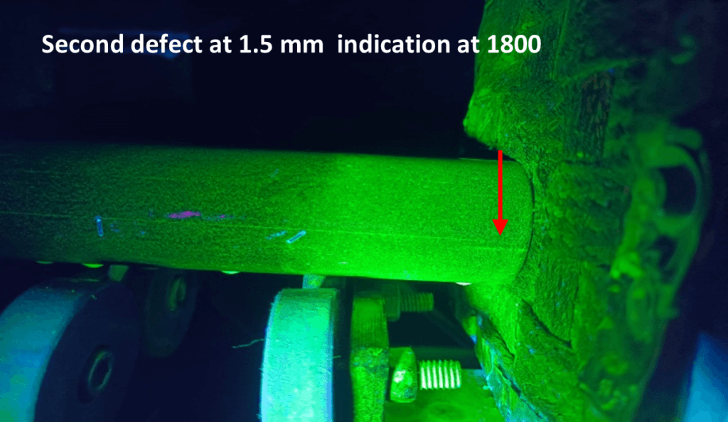
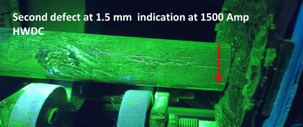
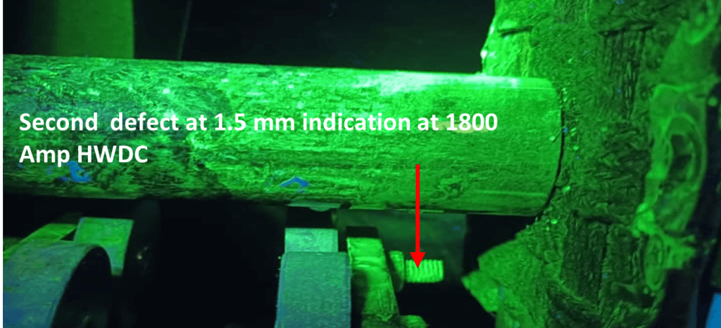
• Slightly Subsurface Defects (D2 – 1.5 mm)
• HWDC outperforms AC 1. Light indication begins at 600 A with HWDC vs 900 A with AC 2. Moderate-to-Strong detection from 900–1800 A with HWDC
• AC remains mostly Light to Moderate even at higher currents
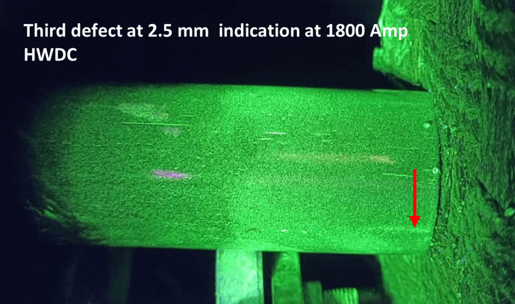
• Deeper Subsurface Defects (D3 – 2.5 mm & D4 – 3.5 mm) 1. AC: No indications at any current level
• HWDC: 1. Moderate visibility of D3 begins at 1500 A 2. Light visibility of D4 at 1500–1800 A
Indication Results :
Comparison: AC vs HWDC Circular Magnetization
Fluorescent MPI – Material: AISI 1050 Steel
Surface Defect Sensitivity (D1 – 0.5 mm)
AC: Best Shim Visibility at 900 A
Only Light at 600 A
Strong indications from 900 A onward
HWDC: Better Shim Visibility at 600 A
Light at 600 A
Strong and consistent from 900 A onward
Subsurface Defect Sensitivity (D2 – 1.5 mm, D3 – 2.5 mm, D4 – 3.5 mm) AC:
No visibility at any current level (surface-only sensitivity)
HWDC:
D2 (1.5 mm): Light at 900 A → Moderate/Strong at 1200–1800 A
D3 (2.5 mm): Light to Moderate indications begin at 1200–1800 A
D4 (3.5 mm): No response observed → deeper depth limit
Indication Results :
Comparison: AC vs HWDC Circular Magnetization
Fluorescent MPI | Material: EN 31
• Shim Indication 1. AC: Strong shim indication achieved at 900 A 2.HWDC: Strong shim indication achieved at 600 A
• Surface Sensitivity (D1 – 0.5 mm) 1. AC: Light at 600–900 A → Strong above 1500 A 2. HWDC: Light at 600 A → Strong from 1200 A onward
• Subsurface Sensitivity
1. AC: • D2 (1.5 mm): Only Light at 1800 A • D3 & D4: Not detected
2. HWDC:
• D2 (1.5 mm): Light → Strong (900–1800 A) • No detection of D3 & D4
Indication Results :
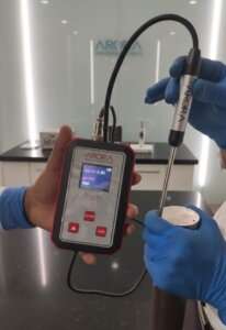
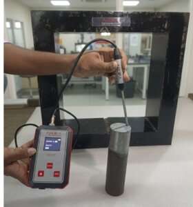
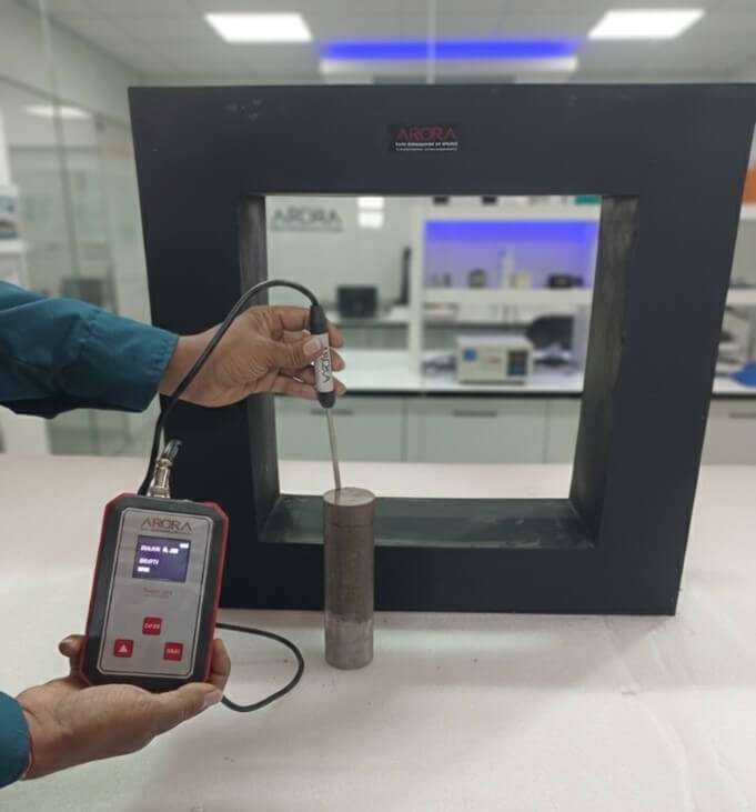
Magnetization & Residual Field Assessment
Specimens were magnetized using Circular Magnetization for MPI inspection
Magnetic field was circumferential, not aligned with Gauss meter sensitivity
Therefore, residual field could not be properly detected
To accurately measure magnetic retention, a Longitudinal Magnetization shot of 1800 A was applied
Re-oriented the field along the length of the component
Allowed the Gauss meter to correctly measure the residual magnetic field
Residual Field After 1800 A Longitudinal Magnetization
Material
Residual Field (Gauss)
1020 Steel
11.74 G
1050 Steel
23.01 G
EN31 Steel
50.83 G
Demagnetization Performance Evaluation
First Demagnetization Attempt
Performed using 11 KAT Demagnetizing Coil
Current applied: 2200 A
Objective: Reduce residual field to an acceptable level (<1–2 Gauss)
Material
Residual Field (Gauss)
1020 steel
0.95 G
1050 Steel
1.61 G
EN31 Steel
4.56 G
Interpretation:
1020 & 1050 nearly at acceptable residual limits
EN31 still above acceptable value → Further demagnetization required
Demagnetization Performance Evaluation
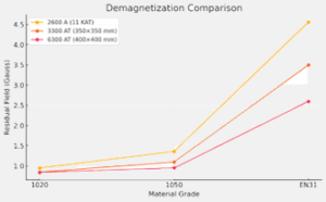
Improved Demagnetization Trials
Performed using larger AT (Ampere-Turn) demag coils:
Coil Setup
1020
1050
EN 31
350 x 350 mm / 3300 AT
0.85 G
1.10 G
3.50 G
400 x 400 mm / 6300 AT
0.84 G
0.95 G
2.60 G
Conclusion
Higher Ampere-turns + Larger coil aperture = More effective demagnetization
EN31 shows highest magnetic retention, requiring stronger demag settings
6300 AT coil achieved lowest residual readings → Recommended for EN31 or hardened steels
Accurate residual field measurement requires proper field orientation ✔ Longitudinal magnetization enabled correct Gauss evaluation
Material grade affects magnetism retention ✔ EN31 (high carbon steel) shows the highest residual field ✔ 1020 and 1050 easier to demagnetize
Demagnetization performance improves with coil strength and aperture ✔ 6300 AT coil demonstrated the most effective demag for all materials
Final residual fields were reduced to safe and acceptable levels ✔ Components can be released for service after verification
In Summary
To ensure reliable MPI inspection and component safety: Choose magnetization and demagnetization techniques based on Material properties, Magnetization direction, expected defect orientation and required Gauss limits.